Physical Layer
Understanding the Physical Layer in the OSI/TCP/IP Model

Introduction
When we think of networking, we often picture IP addresses, data packets, and protocols—but underneath it all lies the Physical Layer, the silent workhorse responsible for the actual transmission of raw data across the network. Whether you’re setting up a home network or building enterprise infrastructure, understanding the physical layer is essential.
In this post, we’ll explore:
- Physical layer functions
- Network topologies
- Transmission media (cables and connectors)
- Twisted pair vs. fiber cables
- Cable types and when to use them
- Straight-through vs. crossover vs. rollover cables
- Coloring standards and Gigabit Ethernet
- MDI/MDI-X, routers, modular connections, and more
What is the Physical Layer?
- The Physical Layer is Layer 1 of the OSI model (and aligns with the Network Interface layer in the TCP/IP model).
- It defines the hardware means of sending and receiving data over a carrier.
- This includes electrical signals, light pulses, connectors, cables, and pinouts.
- It is the most fundamental layer because it deals with the physical medium of communication and how data is actually transmitted from one device to another.
- Without the physical layer, no communication would be possible as there would be no physical path for data to travel.
Functions of the Physical Layer
Bit Transmission- The physical layer is responsible for the transmission and reception of the unstructured raw bit stream over a physical medium.
- It defines the voltage levels and how bits are represented physically, such as in the form of electrical voltage, light signals, or radio waves.
- The physical layer is responsible for the transmission and reception of the unstructured raw bit stream over a physical medium.
Encoding and Signaling- This function involves converting data into signals suitable for the transmission medium.
- Encoding defines how the bits (0s and 1s) are represented as electrical, optical, or radio signals.
Synchronization- It ensures that the sender and receiver are synchronized so that the start and end of each bit are understood by both parties, preventing data corruption.
Topology Control- The physical layer also defines how devices are physically connected, including point-to-point and multipoint topologies, which influence data flow and performance.
Medium Specification- It specifies the characteristics of the transmission medium, such as cable type, connector types, and transmission speed limits, which affect signal quality and range.
Common Physical Topologies
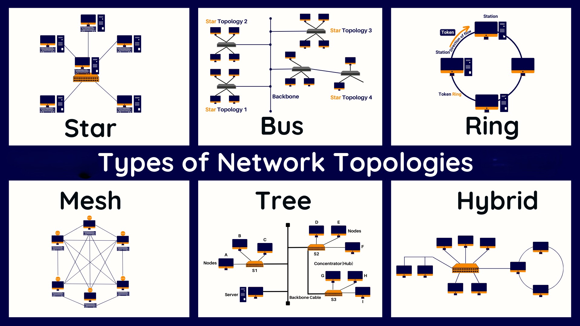
Bus Topology
- All devices share a single communication line. Signals travel in both directions and all devices receive the signals, though only the intended recipient processes it.
- It’s simple and inexpensive but difficult to troubleshoot, and a break in the main cable can bring down the entire network.
Star Topology
- All devices connect to a central hub or switch, which manages and forwards traffic to the appropriate device.
- This topology is easy to manage and expand, and a failure in one cable doesn’t affect the others, making it highly fault-tolerant.
Ring Topology
- Devices are connected in a circular loop. Data travels in one direction and passes through each device until it reaches its destination.
- A failure in any cable or device can disrupt the entire network unless a dual ring is used for redundancy.
Mesh Topology
- Every device is connected to every other device, either fully or partially. This provides high redundancy and reliability, making it ideal for critical systems but expensive and complex to implement.
Hybrid Topology
- Combines elements of other topologies (e.g., star-bus or star-ring) to leverage the advantages of multiple designs while minimizing their drawbacks.
Transmission Media
1. Twisted Pair Cables
- Used extensively in Ethernet networks, these cables consist of pairs of wires twisted together to reduce electromagnetic interference from external sources and crosstalk from neighboring wires.
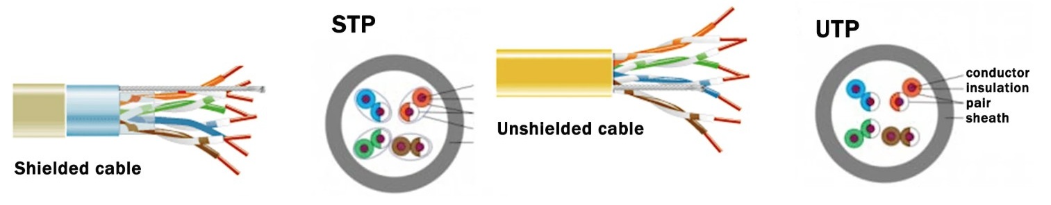
UTP (Unshielded Twisted Pair)- Unshielded twisted pair (UTP) cables are made up of 8 internal wires and are the correct solution for most applications.
- UTP do not rely on physical shielding to block interference and it relies instead on balancing and filtering techniques using media filters, baluns or both.
- It’s cost-effective and widely used in homes and offices, though more vulnerable to interference.
STP (Shielded Twisted Pair)- Shielded cables (STP) are used for increased protection from interference and crosstalk, they are typically used in electrically noisy environments.
- A shielded cable or shield twisted pair (STP) cable has an outside layer or “shield” of conductive material around the internal conductors, which needs to be grounded to cancel the effect of electromagnetic interference (EMI)
Category Max Speed Max Distance Use Cat5e 1 Gbps 100 meters General Ethernet applications Cat6 10 Gbps 55 meters High-speed LANs with short cable lengths Cat6a 10 Gbps 100 meters High-performance commercial networks Cat7/8 40-100 Gbps 10–30 meters Data centers and backbone connections Types of Twisted Pair Cable Connectors:
RJ-45:- The most common connector for data communication, used with unshielded twisted pair (UTP) and shielded twisted pair (STP) cables in Ethernet networks.
- It has 8 pins and is designed to work with four twisted pairs of wires.
RJ-11- Primarily used for telephone systems and modems. It has 4 pins and connects to UTP cables with two twisted pairs.
RJ-48- Similar to RJ-45 but specifically designed for STP cables. It also has 8 pins.
RJ-25- Used for connecting multiple telephone lines, also a twisted-pair connector.
2. Fiber Optic Cables
- Transmit data as light, offering much higher bandwidth and longer distance than copper cables.
Immune to electromagnetic interference and ideal for high-speed, long-distance communication.
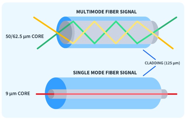
Single-Mode Fiber (SMF)- Uses a single ray of light; provides higher speeds and is suitable for long distances, often used by ISPs and in WAN backbones.
Multi-Mode Fiber (MMF)- Uses multiple rays of light; supports shorter distances and is commonly used within buildings and for short-range communication.
Connectors:- Connectors are crucial components in fiber optic systems, serving as the interface between different devices or fiber optic cables.
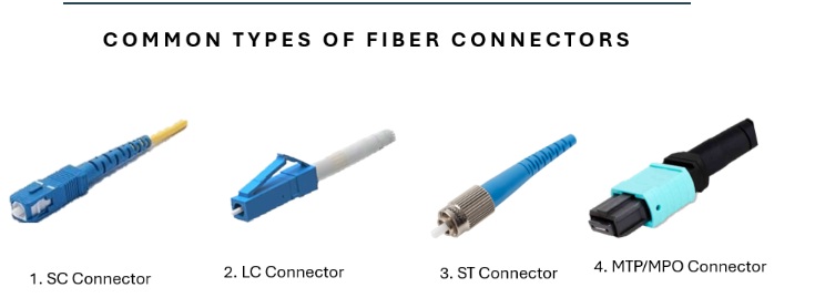
SC (Subscriber Connector)- Uses a push-pull mechanism; more common in enterprise and telecom networks.
- Known for its square shape and excellent repeatability.
- Often used in data centers and FTTH (Fiber to the Home) deployments.
LC (Lucent Connector)- Compact connector with a latch mechanism; widely used in modern networks.
- Ideal for high-density applications due to its small form factor.
- Common in SFP transceivers and enterprise-grade switches.
ST (Straight Tip)- Uses a bayonet-style twist-on mechanism; found in legacy systems.
- Typically used in multimode networks like campuses or legacy buildings.
- Offers reliable performance but is being phased out in favor of modern types.
MTP/MPO (Multi-fiber Push On/Pull Off)- High-density connector that supports multiple fibers (e.g., 12, 24, 48).
- Used in high-speed backbone and data center interconnects.
Characteristic ST (Straight Tip) SC (Subscriber Connector) LC (Lucent Connector) MTP/MPO (Multi-fiber Push On/Pull Off) Year of Introduction Late 1980s Early 1980s 1990s 1990s Application Telecommunications, Industrial, military, datacom, CATV Telecommunications, datacom High-speed data communications, data centers High-density telecommunications, data centers Estimated Life Low to moderate Moderate High High Cost Low Low Low Low Insertion Loss High High High High Return Loss Moderate Moderate High High Durability (Mating Cycles) 1000 500 500 2500 Operating Temperature Range -40°C to +75°C -40°C to +75°C -40°C to +75°C -40°C to +75°C Fiber Compatibility Single-mode and Multimode Single-mode and Multimode Single-mode and Multimode Single-mode and Multimode Size and Footprint Medium Medium Small Large Ease of Use Moderate Moderate High Moderate to High Compliance and Standards TIA/EIA, IEC TIA/EIA, IEC TIA/EIA, IEC TIA/EIA, IEC Polarity Reversibility No No Yes Yes
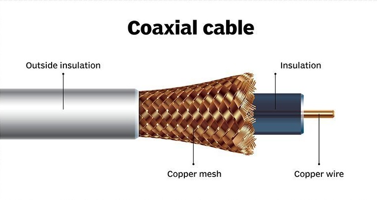
3. Copper Coaxial Cables
Used historically in Ethernet and still used in cable television networks. It has a central conductor, insulation, shielding, and an outer jacket, offering better shielding than twisted pair but less flexibility.
Cable Types & Usage
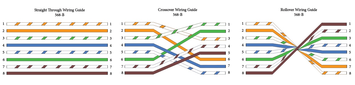
Straight-Through Cable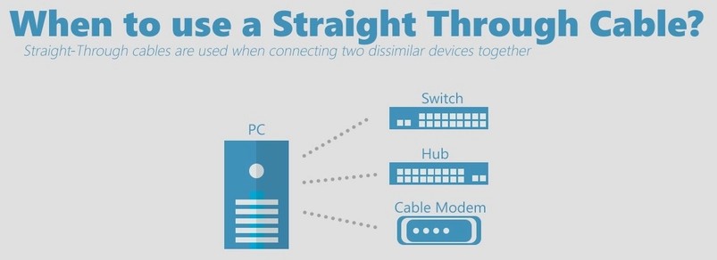
- A straight-through cable is used to connect different types of devices, such as a computer (PC) to a switch or a router to a switch.
- Both ends of the cable follow the same wiring standard, usually T568B, ensuring that the transmit pins on one end align with the receive pins on the other.
- This is the most common type of Ethernet cable used in networking.
Crossover Cable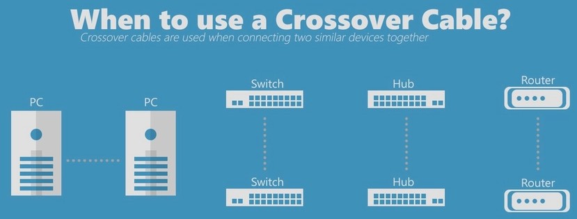
- A crossover cable is used to connect similar devices directly, like PC to PC or switch to switch, without an intermediary device.
- It is wired with one end using the T568A standard and the other end using T568B, which crosses the transmit and receive signal pairs.
- This type of cable is less common today as most modern devices support auto MDI-X, which can automatically configure the connection.
Rollover Cable (Cisco Console Cable)- A rollover cable, often flat and color-coded, is used to connect a computer’s serial port to the console port of Cisco networking devices like routers and switches.
- It has a pinout where each wire is reversed from one end to the other (pin 1 to pin 8, pin 2 to pin 7, etc.).
- This cable is essential for performing initial configurations or troubleshooting when network-based access is unavailable.
Ethernet Wiring Standards
There are two color code standards used for Ethernet cables:
Pin T568A Color T568B Color 1 White/Green White/Orange 2 Green Orange 3 White/Orange White/Green 4 Blue Blue 5 White/Blue White/Blue 6 Orange Green 7 White/Brown White/Brown 8 Brown Brown - A Straight Cable uses the same standard on both ends.
- A Crossover Cable uses T568A on one end and T568B on the other to reverse the transmission paths.
⚡ Gigabit Ethernet & Auto-MDI/MDI-X
- Older network devices required specific cable types based on whether the connected devices were similar or different. This required manual use of straight-through or crossover cables.
- Modern Gigabit Ethernet devices support Auto-MDI/MDI-X, a feature that allows the interface to automatically detect and configure transmit/receive pairs. This means you can use a straight cable in place of a crossover, and the hardware will handle the crossover internally.
✅ Gigabit Ethernet (1000Base-T)
- Supports 1 Gbps speed using all four wire pairs.
- Can auto-negotiate connection using either cable type, due to Auto-MDI/MDI-X.
Modular Routers & Interfaces
- Enterprise routers and switches are often modular, allowing network administrators to insert or remove interface cards based on their needs. These include copper ports, fiber optics, serial interfaces, etc.
- Routers also have
console portsused for direct CLI access. These require rollover cables and terminal emulation software (like PuTTY or Tera Term). Modular design enhances scalability and flexibility in large networks.
When to Use Which Cable?
| Use Case | Cable Type |
|---|---|
| PC to Switch/Router | Straight-through |
| Switch to Switch (older) | Crossover |
| Router to Router (older) | Crossover |
| Console access to Router/Switch | Rollover |
| High-speed backbone | Fiber optic (SMF/MMF) |
| Noisy environments | Shielded Twisted Pair |
| Home/office Ethernet | UTP (Cat5e or Cat6) |
Final Thoughts
The Physical Layer may not get the spotlight, but it’s the bedrock of all communication. The right choice of cables, connectors, and topology can make or break a network—impacting speed, reliability, and maintenance.
As networking evolves toward higher speeds and more fiber-based solutions, understanding these fundamentals will ensure your infrastructure remains future-ready and robust.